Workshop Manuals Demo Manual


 ISUZU COMMERCIAL TRUCK
FSR, FTR, FVR
Equipped with 6 HK1 engine
SERVICE MANUAL (1998)

In order to reduce the chance of personal injury and/or property damage, carefully observe the instructions that follow:
The service manuals of Isuzu Motors America Inc. are intended for use by professional, qualified technicians. Attempting repairs or service without the appropriate training, tools, and equipment could cause injury to you or others. This could also damage the vehicle, or cause the vehicle to operate improperly.
Proper vehicle service and repair are important to the safety of the service technician and to the safe, reliable operation of all motor vehicles. If you need to replace a part, use the same part number or an equivalent part. Do not use a replacement part of lesser quality.
The service procedures we recommend and describe in this service manual are effective methods of performing service and repair. Some of the procedures require the use of tools that are designed for specific purposes.
Accordingly, any person who intends to use a replacement part, a service procedure, or a tool that is not recommended by Isuzu, must first establish that there is no jeopardy to personal safety or the safe operation of the vehicle.
This manual contains various CAUTIONS and NOTICES that you must observe carefully in order to reduce the risk of personal injury during service or repair. Improper service or repair may damage the vehicle or render the vehicle unsafe. These CAUTIONS and NOTICES are not exhaustive. Isuzu can not possibly warn of all the potentially hazardous consequences of your failure to follow these instructions.
This manual covers service procedures to vehicles that are equipped with a Supplemental Inflatable Restraint (SIR). Refer to the CAUTIONS in Cautions and Notices and in Restraints. Refer to SIR component and wiring location views in Restraints before performing a service on or around SIR components or wiring. Failure to follow these CAUTIONS could cause air bag deployment, personal injury, or otherwise unneeded SIR repairs.
In order to help avoid accidental air bag deployment and personal injury, whenever you service a vehicle that requires repair of the SIR and another vehicle system, we recommend that you first repair the SIR, then go on to the other system.


BLANK

New Style Service Manual Structure
This new style service manual is constructed with the following 10 sections:
General Information
Heating, Ventilation, and Air Conditioning (HVAC)
Steering
Suspension
Driveline and Axle
Brakes
Engine
Transmission
Body and Accessories
Restraints
The following table gives the previous service manual sub-sections with the name of the new section and sub-section. Almost all of the diagnosis that was in section SA is now located in its applicable sub-section.
 and Sub-Section Conversion Table
| Old Sub-Section |
Old Sub-Section |
New Section |
Section Name |
Sub-Section Name \ |
| OA |
General Information |
0 |
General Information |
Gen ral Information |
|
OB |
Maintenance and Lubrication |
0 |
General Information |
Mai enance and L brication |
| oc |
Vibration Diagnosis |
0 |
General Information |
Vibration Diagnosis |
| 1A |
Heating and Ventilation |
1 |
HVAC |
Heating and Ventilation (Non NC) |
| 1B |
Heating, Ventilation, and Air Conditioning |
1 |
HVAC |
HVAC systems with Air Conditioning |
| 1D |
NC Compressors |
1 |
HVAC |
HVAC systems with Air Conditioning |
| 2A |
Frame and Bumpers |
8 |
Body and Accessories |
Frame and Underbody, and Bumpers |
| 3A |
Front Wheel Alignment |
3 |
Suspension |
Wheel Alignment |
| 3B, 3B1A, 3B1B |
Power Steering Gear and Pump |
2 |
Steering |
Power Steering System |
| 3B3 |
Steering Linkage |
2 |
Steering |
Steering Linkage |
| 3C |
Front Suspension |
3 |
Suspension |
Front Suspension |
| 3D |
Rear Suspension |
3 |
Suspension |
Rear Suspension |
| 3E |
Tires and Wheels |
3 |
Suspension |
Tires and Wheels |
| 3F |
Steering Columns |
2 |
Steering |
Steering Wheel and Column |
| 4A |
Propeller Shaft |
4 |
Driveline/Axle |
Propeller Shaft |
| 4B |
Rear Axle and Differential |
4 |
Driveline/Axle |
Rear Drive Axle |
|
4C |
Front Drive Axles and Differential |
4 |
Driveline/Axle |
Front Wheel Drive Shafts and Front Drive Axle |
| s |
Hydraulic Brakes |
s |
Brakes |
Hydraulic Brakes |
| SA |
Master Cylinder |
s |
Brakes |
Hydraulic Brakes |
| SB |
Front Disc Brakes |
s |
Brakes |
Disc Brakes |
| SC |
Drum Brakes |
s |
Brakes |
Drum Brakes |
| SD |
Hydraulic or Vacuum Booster |
s |
Brakes |
Hydraulic Brakes |
| SE |
Antilock Brakes |
s |
Brakes |
Antilock Brakes |
| SF |
Parking Brake |
s |
Brakes |
Parking Brake |
| 6, 6A |
Engine Mechanical |
6 |
Engine |
Engine Mechanical |
| 6B |
Engine Cooling and Radiator |
6 |
Engine |
Engine Cooling |
| SC |
Engine Fuel |
6 |
Engine |
Engine Controls |
| 6D |
Engine Electrical |
6 |
Engine |
Engine Electrical |
| – |
Driveability and Emissions |
6 |
– |
Engine Controls |
| 6F |
Exhaust System |
6 |
– |
Exhaust System |
| 6H |
Vacuum Pump |
6 |
Engine |
Vacuum Pump |
| 6J |
Turbocharger |
6 |
Engine |
Turbocharger |
|
7A |
Automatic Transmission |
7 |
Transmission/Transaxle |
Automatic Transmission and Transmission/Transfer Case Unit Repair Manual |

 and Sub-Section Conversion Table (cont’d)
| Old Sub-Section |
Old Sub-Section |
New Section |
Section Name |
Sub-Section Name |
|
78 |
Manual Transmission
7
Transmission/fransaxle
Manual Transmission and Transmission/Transfer Case Unit Repair Manual
7C
Clutch
7
Transmission/fransaxle
Clutch
7D
Transfer Case
4
Driveline/Axle
Transfer Case and Transmission/Transfer Case Unit Repair Manual
88
Lighting Systems
8
Body and Accessories
Lighting Systems
BC
Instrument Panel and Gages
8
Body and Accessories
Instrument Panel, Gages and Console
SD
Chassis Electrical
8
–
Refer to the Index at the end of the manual
BE
Wipers and Washers
8
Body and Accessories
Wiper/Washer Systems
9A
Audio Systems
8
Body and Accessories
Entertainment
98
Cruise Control
8
Body and Accessories
Cruise Control
9E
Engine Coolant Heater
6
Engine
Engine Cooling
9F
Luggage Carrier
8
Body and Accessories
Roof
9J
Supplemental Inflatable Restraint
9
Restraints
Supplemental Inflatable Restraints
9K
Remote Keyless Entry
8
Body and Accessories
Keyless Entry
10A1
Doors
8
Body and Accessories
Doors
10A2
Seats
8
Body and Accessories
Seats
9
Restraints
Seat Belts
10A3
Stationary Windows
8
Body and Accessories
Stationary Glass
10A4
Interior Trim
8
Body and Accessories
Exterior/Interior Trim
10A5
Endgate
8
Body and Accessories
Body Rear End
108
Cab and Body Maintenance
–
–
Refer to the Index at the end of the manual
1998 Medium Duty Truck
FSR,FTR,FVR
Service Manual
Volume 1
This manual provides information on the diagnosis, the service procedures, the adjustments, and the specifications for the 1998 Isuzu Medium Duty Truck.
The technicians who understand the material in this manual and in the appropriate Dealer Service Bulletins better service the vehicle owners.
When this manual refers to a brand name, a part number, or a specific tool, you may use an equivalent product in place of the recommended item. All information, illustrations and specifications in this manual are based on the latest product information available at the time of publication approval. Isuzu reserves the right to make changes at any time without notice.
Published by
ISUZU MOTORS AMERICA, INC.
©1998 ISUZU MOTORS AMERICA, INC.
The information cutoff date is 12/1/97.
ALL RIGHTS RESERVED
LITHO IN U.S.A.

No part of this manual may be reproduced, stored in any retrieval system, or transmitted in any form or by any means (including but not limited to electronic, mechanical, photocopying, and recording) without the prior written permission of Isuzu Motors America, Inc. This applies to all text, illustrations, and tables.


BLANK
Volume 1
Preface 1
Cautions and Notices 3
General Information 0-1
General Information 0-3
Maintenance and Lubrication 0-33
Vibration Diagnosis and Correction 0-51
HVAC 1-1
Heating and Ventilation (Non-A/C) 1-3
HVAC Systems with A/C – Manual. 1-57
Body and Accessories 8-1
Lighting Systems 8-7
Wipers/Washer Systems 8-103
Entertainment 8-123
Wiring Systems 8-143
Instrument Panel, Gauges and Console 8-283
Horns 8-351
Exterior Trim 8-361
Waterleaks 8-363
Stationary Windows 8-365
Bumpers 8-373
Body Front End 8-377
Doors 8-399
Seats 8-431
Interior Trim 8-441
Plastic Panel Information and Repair 8-453
PainVCoatings 8-455
Frame and Underbody 8-463
Collision Repair 8-485
Restraints 9-1
Seat Belts 9-3
Volume2
Preface 1
Cautions and Notices 3
Steering 2-1
Power Steering System 2-3
Steering Linkage (Non-Rack & Pinion) 2-53
Steering Wheel and Column – Tilt. 2-63
Suspension ………………..…………………………..3..–.1…
Suspension General Diagnosis 3-3
Wheel Alignment. 3-17
Front Suspension 3-25
Rear Suspension 3-63
Tires and Wheels 3-87
Air Suspension 3-107
Driveline/Axle 4-1
Propeller Shaft 4-3
Rear Drive Axle 4-63
Rear Axle Controls 4-89
Brakes 5-7
Hydraulic Brakes 5-7
Disc Brakes 5-41
Park Brakes 5-89
Air Brakes 5-113
Air Drums 5-227
Air Compressor 5-287
Antilock Brake System 5-303
Air Antilock Brake System 5-399
Volume3
Preface 1
Cautions and Notices 3
Engine 6-1
Engine Cooling 6-3
Engine Electrical 6-43
Engine Controls – 7.8L. 6-111
Engine Exhaust. 6-137
Engine, On-vehicle Service 6A6
Engine Overhaul. 6A6B
Water Pump 661B
Fuel System 6C
Fuel Injection 6C2
Diesel Electrical 606
Emission and Electrical Diagnosis 6E
Turbocharger 6J
Transmissionrrransaxle………...………………..1..–.1.
Manual Transmission – Medium Duty 7-3
Automatic Transmission – Allison 7-15
Clutch 7-43
Manual Transmission Overhaul. 7-49

1998 • MD•ISUZU
BLANK


Cautions and Notices
Cautions and Notices 3
Definition of Caution, Notice, and lmportant. 3
ABS Handling Caution 3
Battery Disconnect Caution 3
Brake Dust Caution 3
Brake Fluid Caution 4
Clutch Dust Caution 4
Fuel and EVAP Pipe Caution 4
Fuel Gauge Leak Caution 4
Fuel Pipe Fitting Caution 4
Fuel Storage Caution 4
Gasoline/Gasoline Vapors Caution 4
Moving Parts and Hot Surfaces Caution 4
Road Test Caution 4
Safety Glasses and Compressed
Air Caution 4
Safety Goggles and Fuel Caution 4
Vehicle Lifting Caution 4
Window Removal Caution 4
Work Stall Test Caution 5
Defective Scan Tool Notice 5
Fastener Notice 5
Fuel Pressure Notice 5
Handling ESD Sensitive Parts Notice 5
Ignition OFF When Disconnecting
Battery Notice 5
Nylon Fuel Lines Notice 5
PCM and ESD Notice 5
Single Cylinder Flooding Notice 5

1998 – MD-Isuzu


BLANK
1998 – MD-Isuzu
Preface Cautions and Notices – 3


Cautions and Notices

Definition of Caution, Notice, and Important
The diagnosis and repair procedures in the Isuzu Service Manual contain both general and specific Cautions, Notices, and lmportants. Isuzu is dedicated to the presentation of service information that helps the technician to diagnose and repair the systems necessary for the proper operation of the vehicle, however, certain procedures may present a hazard to the technician if they are not followed in the recommended manner. Cautions, Notices, and lmportants are elements designed to prevent these hazards, however, not all hazards can be foreseen.
This information is placed at strategic locations within the service manual. This information is designed to prevent the following from occurring:
Serious bodily injury to the technician
Damage to the vehicle
Unnecessary vehicle repairs
Unnecessary component replacement
Improper repair or replacement of vehicle components. Any caution or notice that appears in general information is referenced from the individual service categories.
CAUTION Defined
When encountering a CAUTION, you will be asked to take a necessary action or not to take a prohibited action. If a CAUTION is not heeded, the following consequences may occur:
Serious bodily injury to the technician
Serious bodily injury to other technicians in the workplace area
Serious bodily injury to the driver and/or passenger(s) of the vehicle, if the vehicle has been improperly repaired
NOTICE Defined
Notices call special attention to a necessary action or to a prohibited action. If a NOTICE is not heeded, the following consequences may occur:
Damage to the vehicle
Unnecessary vehicle repairs
Unnecessary component replacement
Improper operation or performance of the system or component under repair
Damage to any systems or components which are dependent upon the proper operation of the system or component under repair
Improper operation or performance of any systems or components which are dependent upon the proper operation or performance of the system or component under repair
Damage to fasteners, basic tools, or special tools
The leakage of coolant, lubricant, or other vital fluids
1998 – MD-Isuzu
IMPORTANT Defined
IMPORTANT statements emphasize a necessary characteristic of a diagnostic or repair procedure.
IMPORTANT statements are designed to do the following:
Clarify a procedure
Present additional information for accomplishing a procedure
Give insight into the reason or reasons for performing a procedure in the manner recommended
Present information that will help to accomplish a procedure in a more effective manner
Present information that gives the technician the benefit of past experience in accomplishing a procedure with greater ease
ABS Handling Caution
Caution: Certain components In the Antilock Brake System (ABS) are not intended to be serviced individually. Attempting to remove or disconnect certain system components may result in personal injury and/or improper system operation. Only those component with approved removal and installation procedures should
be serviced.
Battery Disconnect Caution
Caution: Before servicing any electrical component, the ignition key must be in the OFF or LOCK position and all electrical loads must be OFF, unless instructed otherwise in these procedures. If a tool or equipment could easily come in contact with a live exposed electrical terminal, also disconnect the negative battery cable. Failure to follow these precautions may cause personal injury and/or damage to the vehicle or its components.
Brake Dust Caution
Caution: Avoid taking the following actions when you service wheel brake parts:
Do not grind brake linings.
Do not sand brake linings.
Do not clean wheel brake parts with a dry brush or with compressed air.
Some models or aftermarket brake parts may contain asbestos fibers which can become airborne in dust. Breathing dust with asbestos fibers may cause serious bodily harm. Use a water-dampened cloth in order to remove any dust on brake parts. Equipment Is available commercially in order to perform this washing function. These wet methods prevent fibers from becoming airborne.


 4 – Cautions and Notices Preface
Brake Fluid Caution
Caution: Brake fluid may be irritating to the skin or eyes. In case of contact, take the following actions:
Eye contact-rinse eyes thoroughly with water.
Skin contact-wash skin with soap and water.
Clutch Dust Caution
Caution: When servicing clutch parts, do not create dust by grinding or sanding the clutch disc or by cleaning parts with a dry brush or with compressed air. A water-dampened
cloth-NOT SOAKED-should be used. The clutch disc contains asbestos fibers which can become airborne If dust is created during servicing.
Breathing dust containing asbestos fibers may cause serious bodily harm.
Fuel and EVAP Pipe Caution
Caution: In order to Reduce the Risk of Fire and Personal Injury observe the following Items:
Replace all nylon fuel pipes that are nicked, scratched or damaged during Installation, Do Not attempt to repair the sections of the nylon fuel pipes
Do Not hammer directly on the fuel harness body clips when insta/1/ng new fuel pipes. Damage to the nylon pipes may result In a fuel leak.
Always cover nylon vapor pipes with a wet towel before using a torch near them. Also, never expose the vehicle to temperatures higher than 11s·c (239″F) for more than one hour, or more than 90″C (194°F) for any extended period.
Apply a few drops of clean engine oil to the male pipe ends before connecting fuel pipe fittings. This will ensure proper reconnection and prevent a possible fuel leak. (During normal operation, the O-rings located In the female connector will swell and may prevent proper reconnection if not lubricated.)
Fuel Gauge Leak Caution
Caution: Wrap a shop towel around the fuel pressure connection in order to reduce the risk of fire and personal injury. The towel will absorb any fuel leakage that occurs during the connection of the fuel pressure gauge. Place the towel In an approved container when the connection of the fuel pressure gauge is complete.
Fuel Pipe Fitting Caution
Caution: Always apply a few drops of clean engine oil to the male pipe ends before connecting fuel pipe fittings In order to reduce the risk of fire and personal injury.
This w/11 ensure proper reconnection and prevent a possible fuel leak.
During normal operation, the O-rings located in the female connector will swell and may prevent proper reconnection if not lubricated.
Fuel Storage Caution
Caution: Do not drain the fuel into an open container. Never store the fuel In an open container due to the possibility of a fire or an explosion.
Gasoline/Gasoline Vapors Caution
Caution: Gasoline or gasoline vapors are highly flammable. A fire could occur If an ignition source is present. Never drain or store gasoline or diesel fuel in an open container, due to the possibility of fire or explosion. Have a dry chemical (Class BJ fire extinguisher nearby.
Moving Parts and Hot Surfaces Caution
Caution: While working around a running engine, avoid contact with moving parts and hot surfaces to prevent possible bodily injury.
Road Test Caution
Caution: Road test a vehicle under safe conditions and while obeying all traffic laws. Do not attempt any maneuvers that could Jeopardize vehicle control. Failure to adhere to these precautions could lead to serious personal Injury.
Safety Glasses and Compressed Air Caution
Caution: Wear safety glasses when using compressed air in order to prevent eye injury.
Safety Goggles and Fuel Caution
Caution: Always wear safety goggles when working with fuel In order to protect the eyes from fuel splash.
Vehicle Lifting Caution
Caution: To help avoid personal Injury, when a vehicle Is on a hoist, provide additional support for the vehicle at the opposite end from which you are removing components. The additional support will reduce the possibility of the vehicle falling off the hoist. When you are removing major components· from the vehicle while the vehicle Is on a hoist, chain the vehicle frame to the hoist pads at the same end from which you are removing the major components to prevent tip-off. If you fall to follow these precautionary measures, vehicle damage, serious personal Injury, or death may result.
Window Removal Caution
Caution: When working with any type of glass, use approved safety glasses and gloves to reduce the chance of personal injury.
1998 – MD-Isuzu


Caution: One or more of the following guidelines may apply when performing specific required tests in the work stall:
When a test requires spinning the drive wheels with the vehicle jacked up, adhere to the following precautions:
Do not exceed 56 km/h (35 mph} when spinning one drive wheel with the other drive wheel stopped. This limit is necessary because the speedometer indicates only one-half the actual vehicle speed under these conditions. Personal injury may result from excessive wheel spinning.
– If all of the drive wheels are spinning at the same speed, do not exceed 112 km/h (70 mph}. Personal injury may result from excessive wheel spinning.
All persons should stay clear of the rotating components and the balance weight areas in order to avoid possible personal injury.
When running an engine in the repair stall for an extended period of time, use care not to overheat the engine and the transmission.
When a test requires jacking up the vehicle and running with the wheels and brake rotors removed, adhere to the following precautions:
Do not apply the brake with the brake rotors removed.
Do not place the transmission in PARK
with the drive wheels still spinning.
Turn Off the ignition in order to stop the powertrain components from spinning.
Defective Scan Tool Notice
Notice: Do not use a scan tool that displays faulty data. Report the scan tool problem to the manufacturer. Use of a faulty scan tool can result in misdiagnosis and unnecessary parts replacement.
Fastener Notice
Notice: Use the correct fastener in the correct location. Replacement fasteners must be the correct part number for that application. Fasteners requiring replacement or fasteners requiring the use of thread locking compound or sealant are identified in the service procedure. Do not use paints, lubricants, or corrosion inhibitors on fasteners or fastener joint surfaces unless specified. These coatings affect fastener torque and joint clamping force and may damage the fastener. Use the correct tightening sequence and specifications when installing fasteners in order to avoid damage to parts and systems.
Fuel Pressure Notice
Notice: Do not allow the fuel pressure to exceed the specified value because damage to the fuel pressure regulator or the fuel pressure gauge may result.
1998 – MD-Isuzu
Handling ESD Sensitive Parts Notice
Notice: Electrostatic discharge (ESD) can damage many solid-state electrical components. ESD susceptible components may or may not be labeled with the ESD symbol. Handle all electrical components carefully. Use the following precautions in order to avoid ESD damage:
Touch a metal ground point in order to remove your body’s static charge before servicing any
electronic component; especially after sliding across the vehicle seat.
Do not touch exposed terminals. Terminals may connect to circuits susceptible the ESD damage.
Do not allow tools to contact exposed terminals when servicing connectors.
Do not remove components from their protective packaging until required to do so.
Avoid the following actions unless required by the diagnostic procedure:
Jumpering or grounding of the components or connectors.
Connecting test equipment probes to components or connectors. Connect the ground lead first when using test probes.
Ground the protective packaging of any component before opening. Do not rest solid-state components on metal workbenches, or on top of TVs, radios, or other electrical devices.
Ignition OFF When Disconnecting Battery Notice
Notice: Always turn the ignition OFF when connecting or disconnecting battery cables, battery chargers, or jumper cables. Failing to do so may damage the Powertrain Control Module (PCM) or other electronic components.
Nylon Fuel Lines Notice
Notice: Do not attempt to straighten the kinked nylon fuel lines. Replace any kinked nylon fuel feed or return pipes in order to prevent damage to the vehicle.
PCM and ESD Notice
Notice: Do not touch the connector pins or soldered components on the circuit board in order to prevent possible electrostatic discharge (ESD) damage to the PCM.
Single Cylinder Flooding Notice
Notice: In order to prevent flooding of a single cylinder and possible engine damage, relieve the fuel pressure before performing the fuel injector coil test procedure.


BLANK
1998 – MD-Isuzu
General Information Table of Contents 0-1


Section O
General Information
General Information 0-3
Conversion – English/Metric 0-3
Equivalents – Decimal and Metric 0-3
Paper Version of the Service Manual –
How to Use 0-4
Arrows and Symbols 0-5
Special Tools Ordering Information 0-5
Vehicle ldentification 0-5
VIN Derivative 0-6
Label – Vehicle Certification 0-7
Engine Identification 0-8
Transmission Identification 0-8
Rear Axle Identification 0-9
Label – Service Parts ID 0-11
RPO Code List 0-11
Labels – How to Obtain Replacement. 0-17
Fasteners (Prevailing Torque Fasteners) 0-17
Fasteners (Strength Identification) 0-19
Fasteners (Metric Fasteners) 0-20
Thread Inserts 0-20
Torque Wrenches 0-21
Abbreviations and Their Meanings 0-23
Key and Lock Cylinder Coding 0-26
Lifting and Jacking the Vehicle 0-26
Cab Tilting 0-27
Towing a Disabled Vehicle 0-30
Strategy Based Diagnosis 0-32
Maintenance and Lubrication 0-33
Specifications 0-33
Approximate Fluid Capacities 0-33
Fluid and Lubricant Recommendations 0-34
Maintenance Items 0-34
Maintenance 0-35
Maintenance Schedule 0-35
Maintenance Schedule – Short Trip/City 0-43
Maintenance Schedule –
Long Trip/Highway 0-43
Owner Checks and Services (General) 0-43
Owner Checks and Services (Single Axle) 0-46
Explanation of Scheduled Services 0-47
Inspections and Other Services 0-50
Vibration Diagnosis and Correction 0-51
Specifications 0-51
Specifications 0-51
Diagnostic Information and Procedures 0-52
Systematic Approach 0-52
Vibration Diagnosis 0-52
Road Test 0-52
Classifying the Vibration 0-56
Tire and Wheel Vibration …….; 0-59
Tire and Wheel Runout Measurement 0-59
Driveline Vibration Analysis with EVA 0-63
Engine Related Vibration 0-67
Repair Instructions 0-71
General Service Precautions 0-71
Correcting Tire and Wheel Vibration 0-71
Balancing Tires and Wheels 0-71
Wheel Weight Usage 0-75
Correcting Non-Uniform Tires 0-75
Correcting Driveline Vibration –
RWD and 4WD 0-76
Description and Operation 0-94
General Description 0-94
Special Tools and Equipment. 0-105

1998 – MD-Isuzu


0-2 Table of Contents General Information


BLANK
1998 – MD-Isuzu


In order to convert English units to metric units, multiply the English units by the conversion factor shown in the conversion table.
In order to convert metric units to English units, divide the metric units by the conversion factor shown in the conversion table.
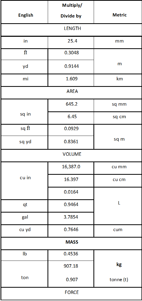 Conversion – English/Metric
1998 – MD-Isuzu
Conversion – English/Metric (cont’d)
|
English |
Multiply/ Divide by |
Metric |
| PRESSURE (STRESS) | ||
| inches of Mercury |
3.377 |
kPa |
| inches of H2O |
0.2491 |
kPa |
| lb/sq in |
6.895 |
|
| LIGHT | ||
| Foot Candle |
10.764 |
2 lm/m |
| VELOCITY | ||
| mph |
1.6093 |
km/h |
| TEMPERATURE | ||
| ‘F |
5/9( • F-32) |
·c |
| ·c |
9/5(‘C+32) |
‘F |
| FUEL PERFORMANCE | ||
| mpg |
2.3527 |
Ukm |
Refer to the following table for equivalent of fractions to decimals in English (inches), to metric (millimeters).
Equivalents – Decimal and Metric
| Fraction (in) |
Decimal (in) |
Metric (mm) |
| 1/64 |
0.015625 |
0.39688 |
| 1/32 |
0.03125 |
0.79375 |
| 3/64 |
0.046875 |
1.19062 |
| 1/16 |
0.0625 |
1.5875 |
| 5/64 |
0.078125 |
1.98437 |
| 3/32 |
0.09375 |
2.38125 |
| 7/64 |
0.109375 |
2.77812 |
| 1/8 |
0.125 |
3.175 |
| 9/64 |
0.140625 |
3.57187 |
| 5/32 |
0.15625 |
3.96875 |
| 11/64 |
0.171875 |
4.36562 |
| 3/16 |
0.1875 |
4.7625 |
| 13/64 |
0.203125 |
5.15937 |
| 7/32 |
0.21875 |
5.55625 |
| 15/64 |
0.234375 |
5.95312 |
| 1/4 |
0.25 |
6.35 |
| 17/64 |
0.265625 |
6.74687 |
| 9/32 |
0.28125 |
7.14375 |
| 19/64 |
0.296875 |
7.54062 |
| 5/16 |
0.3125 |
7.9375 |
| 21/64 |
0.328125 |
8.33437 |
 Equivalents – Decimal and Metric (cont’d)
| Fraction (in) |
Decimal (in) |
Metric (mm) |
| 11/32 |
0.34375 |
8.73125 |
| 23/64 |
0.359375 |
9.12812 |
| 3/8 |
0.375 |
9.525 |
| 25/64 |
0.390625 |
9.92187 |
| 13/32 |
0.40625 |
10.31875 |
| 27/64 |
0.421875 |
10.71562 |
| 7/16 |
0.4375 |
11.1125 |
| 29/64 |
0.453125 |
11.50937 |
| 15/32 |
0.46875 |
11.90625 |
| 31/64 |
0.484375 |
12.30312 |
| 1/2 |
0.5 |
12.7 |
| 33/64 |
0.515625 |
13.09687 |
| 17/32 |
0.53125 |
13.49375 |
| 35/64 |
0.546875 |
13.89062 |
| 9/16 |
0.5625 |
14.2875 |
| 37/64 |
0.578125 |
14.68437 |
| 19/32 |
0.59375 |
15.08125 |
| 39/64 |
0.609375 |
15.47812 |
| 5/8 |
0.625 |
15.875 |
| 41/64 |
0.640625 |
16.27187 |
| 21/32 |
0.65625 |
16.66875 |
| 43/64 |
0.671875 |
17.06562 |
| 11/16 |
0.6875 |
17.4625 |
| 45/64 |
0.703125 |
17.85937 |
| 23/32 |
0.71875 |
18.25625 |
| 47/64 |
0.734375 |
18.65312 |
| 3/4 |
0.75 |
19.05 |
| 49/64 |
0.765625 |
19.44687 |
| 25/32 |
0.78125 |
19.84375 |
| 51/64 |
0.796875 |
20.24062 |
| 13/16 |
0.8125 |
20.6375 |
| 53/64 |
0.828125 |
21.03437 |
| 27/32 |
0.84375 |
21.43125 |
| 55/64 |
0.859375 |
21.82812 |
| 7/8 |
0.875 |
22.225 |
| 57/64 |
0.890625 |
22.62187 |
| 29/32 |
0.90625 |
23.01875 |
| 59/64 |
0.921875 |
23.41562 |
| 15/16 |
0.9375 |
23.8125 |
| 61/64 |
0.953125 |
24.20937 |
| 31/32 |
0.96875 |
24.60625 |
| 63/64 |
0.984375 |
25.00312 |
| 1 |
1.0 |
25.4 |
Paper Version of the Service Manual –
How to Use
Construction
This service manual is constructed with the following 1O major sections:
| Major Section Number |
Major Section Name |
| 0 |
General Information |
| 1 |
Heating, Ventilation, and Air Conditioning (HVAC) |
| 2 |
Steering |
| 3 |
Suspension |
| 4 |
Driveline/Axle |
| 5 |
Brakes |
| 6 |
Engine |
| 7 |
Transmission/Transaxle |
| 8 |
Chassis/Body Electrical |
| 9 |
Accessories |
| 10 |
Body |
Information Flow
Each major section will be structured as follows:
A single table of contents for the entire major section; including all contents of the subsections within the major section.
Subsections
The service information located within each subsection will be ordered as follows:
Specifications
Diagnosis
Repair procedures
General description and system operation
Special tools
Improvements Made
This service manual provides many more illustrations than in earlier manuals. Illustrations serve as the primary source for repair procedures. These illustrations will be supplemented with text descriptions. In the previous service manuals, text was the primary source of information for repair procedures and illustrations provided support.
Repair procedures, illustrations, and the descriptive text have been arranged so that they will correspond with the way you work. This manual provides disassembled views, wherever possible, so that it will be easy to look up parts, names, and order of assembly. The text descriptions have been rewritten into simple, complete sentences.